Polymer Insulator Manufacturing Process
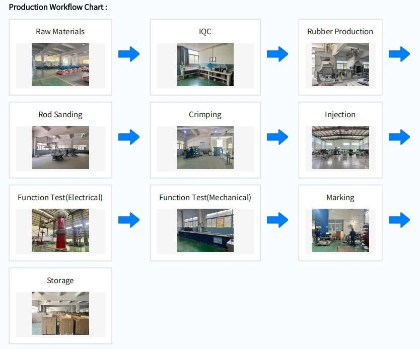
Raw Material Inspection( The Fiberglass Rod)
The insulator's core rod is made of high-temperature resistant, corrosion-resistant, or acid-resistant material. The core rods must undergo sampling tests, including water diffusion tests, red-light absorption tests, tensile tests, and corrosion resistance tests, as well as individual visual inspections and electrical tests, before being put into storage. Furthermore, the core rods must undergo physical and chemical treatments before being used in production; otherwise, the bonding between the core rod and silicone rubber will result in rubber damage. During production, random checks of the water diffusion and red-light absorption tests at the core rod-sheath interface are also conducted.


Rubber Production( Silicone Rubber)
Silicone rubber materials offer better hydrophobicity and aging resistance compared to earlier materials such as epoxy resin, ethylene propylene rubber, and room-temperature vulcanized silicone rubber. Therefore, they have superior resistance to flashover caused by pollution. Currently, the rubber compound formulations are further optimized, and the aluminum hydroxide powder material in the compound is processed through activation treatment to significantly improve its hydrophobicity. High-end silicone products use imported D4 monomer raw materials, further enhancing their anti-aging performance.


Grinding( The Fiberglass rod)
Automatic Mandrel Grinding
To improve the production efficiency and uniformity of mandrel grinding, our company uses a grinding machine to grind the mandrels. This process ensures both the efficiency and quality of mandrel grinding.


Crimping (The fiberglass rod and the end fittings)
The fittings and mandrel are connected by a crimping method. Since the end crimping involves connecting two different materials, we strictly control the elastic modulus, tensile strength, compressive strength, and structural dimensions of both the mandrel and fitting materials. The fitting structure is designed with stress-relieving arcs to ensure uniform stress on the mandrel. The entire crimping process is computer-controlled, and the results are monitored by an acoustic wave detector to ensure the quality of each product.


Injection
5.1)Silicone rubber is injected into a mold and cured under high temperature and pressure to form a single integrated unit. The injection is carried out in segments according to the final length of the insulator.
The purpose of an injection molding machine is to inject sheds and sheaths into composite insulators and perform vulcanization molding. Vulcanization is the process of crosslinking a highly malleable linear silicon-oxygen molecular structure compound into a network of silicon-oxygen molecular structures with a fixed shape under high temperature, high pressure, and a specific time. This crosslinks with the mandrel to form a unified whole.
Injection molding machines are classified by clamping force. Commonly used injection molding machines for composite insulators include 200, 300, 500, 550, 660, 880, 1100, and 1800 tons.
The maximum injection volume can reach 50,000 CC. 300-ton and 500-ton machines are the most widely used.


5.2) To prevent eccentricity during injection, mandrel ejector pins are used on the left and right sides of the mold to control vertical eccentricity, and a synchronization bracket is installed on the mold to further control vertical eccentricity. A portable ultrasonic non-destructive thickness gauge is also used to check the sheath thickness to ensure that the product sheath meets standard requirements.


Function Test( Electrical)
6.1)Creepage distance:
The shortest distance or sum of shortest distances along the surface between conductive parts of an insulator under normal operating voltage.
Note 1: The surface of cement or other non-insulating bonding materials cannot be included in the creepage distance.
Note 2: If a high-resistance layer is applied to the insulating part of the insulator, this insulating part is considered an effective insulating surface, and its surface distance is included in the creepage distance.
6.2) Arcing distance:
The shortest distance in the external space between two metal parts of an insulator that are normally under operating voltage.
6.3)Dry lightning impulse withstand voltage test
The dry lightning impulse withstand voltage test is conducted to verify that the insulator can endure the lightning-induced overvoltages it may be exposed to during actual operation.
6.4)Wet power-frequency test
This test is performed to confirm that the insulator can endure the one-minute power frequency voltage under wet conditions.

Function Test( Mechanical)
7.1)Visual examination
Each insulator shall be examined. The mounting of the end fittings on the insulating parts shall be in accordance with the drawings. The colour of the insulator shall be approximately as specified in the drawings. The markings shall be in conformance with the requirements of this standard
7.2)Mechanical routine test
Every insulator shall withstand, at ambient temperature, a tensile load at RTL corresponding to 0,5 × SML ( +10 ) % for at least 10 s.


Marking
According to the customer's requirements, the markings can be printed either on the sheds or on the fittings. The markings on the sheds are laser-printed.

