
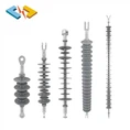

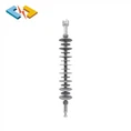

Products Parameters

| Model | System Voltage (kV) |
Height (mm) |
Dry Arcing Distance (mm) |
Creepage Distance (mm) |
Specified Cantilever Load (SCL) |
Max. Working Cantilever Load (MDCL) |
Power Frequency Withstand Voltage (Wet/Dry) |
Lightning Impulse Withstand Voltage |
| FZSW-69/26.8 | 69 | 814±10 | 660 | 1895 | 26.8kN | 12kN | 170kV/200kV | 385kV |

technology characteristics
Silicone Rubber Housing
- Better hydrophobicity
- Better hydrophobicity migration performance
- Better pollution resistance
- Excellent electrical insulation properties
- Excellent aging resistance
| Item | Requirement | Measured Valued |
| Visual examination | Fuchsine, grey or white, no obvious mechanical admixture. Vulcanized silicon rubber with dense and smooth cutting surface. | Ok |
| Hardness (shore A) | ≮50 | 65~70 |
| Tensile strength (Map) | ≮4 | 4~6 |
| Failure elongation (%) | ≮150 | ≮180 |
| Tearing strength (kN/m) | ≮10 (right angle sample) | 12~15 |
| Volume resistivity (Ω.m) | 1X10¹² | 3~8X10¹² |
| Puncture strength (kV/mm) | Alternating current ≮22 | ≮30 |
| Tracking and erosion | TMA4.5,erosion depth≯2.5mm | TMA4.5, erosion depth <0.8mm |
| Flammability (Grade) | FV-0 | FV-0 |
Corrosive Resistance Fiberglass Core
Excellent resistance to high temperature, stress corrosive & acid attack
Better damping Performance
High tensile strength (>1200Mpa)
Excellent creep resistance
Excellent anti-fatigue fracture properties
Crimping & Multiple Sealing
High mechanical strength
Small dispersion
Reliable sealing performance between rods and end fittings

certificates
IEC 62231, ISO 9001, ISO 45001, ISO 14001, etc. We can design products in accordance with Client's Requirements.

knowledge
12 common electrical problems and their solutions 7-12
The installation of lamps and ceiling fans does not meet the requirements
1. Phenomenon
(1) The lamp position is installed offset and not at the center point.
(2) The horizontality and straightness deviation of rows of lamps is large.
(3) The hanging chain fluorescent lamp chain is not parallel and the leading wires are not braided.
(4) The hook of the ceiling fan is made of rebar and is poorly formed; the bell jar does not absorb the ceiling and the junction box is exposed.
(5) The iron plate of the balcony lamp chassis fell off and became rusty.
(6) The simple lamp openings on the ceiling are large and uneven.
2. Cause analysis
(1) The position of the pre-embedded light box was wrong and there was deviation, and no remedial measures were taken when installing the lamps.
(2) The construction personnel have a weak sense of responsibility and are not familiar with the current construction and acceptance specifications and quality inspection and assessment standards.
(3) When buying lamps, the buyer is just trying to make a statement and ignores the quality;
(4) When opening the downlight hole, the size, location, and diameter of the round hole are not determined, etc.
3. Preventive measures
(1) Before installing lamps, the center point should be carefully identified and deviations corrected in a timely manner.
(2) According to the specifications, the deviation in the installation of rows of lamps should not be greater than 5mm. Therefore, it is necessary to position the wires during construction so that the lamps are in a straight line longitudinally, transversely, obliquely, and at the main and lower levels.
(3) The hanging chains of fluorescent lamps should be straight to each other and should not appear in a figure-eight shape. The wire leads should be intertwined with the hanging chains.
(4) When pre-embedding ceiling fan hooks, galvanized round steel no less than Ф8 should be fixed with the steel bars in the plate. Rebar is not allowed. The hooks should be processed and formed uniformly and painted with anti-rust paint. The ceiling fan bell covers the ceiling and covers the hook and junction box. Rows of ceiling fans should be in a straight line with a deviation of ≤5mm.
(5) The thickness of the iron plate of the bottom box of the balcony lamp is ≥0.5mm, and the paint surface is even and smooth, which can effectively prevent rust; the glass cover should not be too thin to avoid cracking during installation.
(6) The coordinates of the downlight openings in the ceiling must be determined first. In addition to being straight, neat and equal, the size of the openings must comply with the specifications of the downlights and must not be too large to ensure that the outer ring is securely attached when the downlights are installed. Fits tightly to the ceiling without exposing any gaps.
(7) Construction personnel and purchasing personnel must conscientiously implement relevant national and local regulations.
The installation of cables and busbars does not meet the requirements
1. Phenomenon
(1) The cables are not uniformly listed after installation, and the cables are laid in a messy manner in cable trenches and bridges.
(2) In the shaft, the cable holes are not tightly sealed; the brackets for vertically fixing the cables are too small, too soft, and tilt downward.
(3) The cable is not tightly sealed after passing through the entrance pipe.
(4) The terminal block (wire lug) is too large or too small, the wall is too thin, and it will break when crimping the joint.
(5) The busbar plug-in box is not installed straight, and each section of the busbar is too long, making it difficult to transport and install.
2. Cause analysis
(1) The various cable construction units did not coordinate well and only hoped that the cables they laid could pass through.
(2) There was no coordination with the civil engineering unit when sealing the high-voltage shaft, and the construction workers did not master the sealing technology.
(3) The materials are not up to standard and the purchasing personnel do not purchase cable fixing brackets and terminals (wire lugs) in accordance with the standards.
(4) The area left by the architectural major to the electrical major to build strong current shafts is too small, making it difficult to lay out strong current shafts.
3. Preventive measures
(1) The cable construction team must coordinate well, arrange the direction and location of large and small cables respectively, and after installation, use moisture-proof and anti-corrosion paper tags to list them, indicating the line number, model, specification and starting and ending points of various spline cables. . The listed locations are: cable terminal head, cornering philosophy, inside the mezzanine, both ends of the shaft, manual holes in the cable trench, etc.
(2) Use a mixture of hemp wire and asphalt to seal the hole through which the shaft cable passes. When there is an outdoor entrance pipe to the basement, the pipe opening must be waterproofed. These tasks require close cooperation with the civil engineering profession. Clean the site after sealing.
(3) When purchasing cable rounding brackets, terminal blocks (wire lugs) and other materials in the purchasing room, they must be purchased in accordance with the specifications. When crimping joints, accurately select the corresponding hydraulic pliers and corresponding kit.
(4) When ordering busbars, it must be ensured that each busbar section shall not be greater than the height of each floor; generally no greater than 3 meters to facilitate transportation and installation in the building.
(5) When busbars and accessories enter the site, they must be inspected strictly in accordance with GBJ149-90 "Code for Construction and Acceptance of Busbar Devices in Electrical Device Installation Engineering" and the contract.
(6) When installing the plug-in box, it should be horizontally and vertically, and the contact with the busbar should be reliable and firm.
The laying of indoor and outdoor cable trench structures and cable tubes does not meet the requirements
1. Phenomenon
(1) The cable trench and concrete bracket are not installed straight and are easy to break.
(2) Cable trenches and cable pipes have poor drainage.
(3) The cable passing pipe is not buried deep enough, and the bell mouth is cracked and irregular.
(4) The anti-rust and anti-corrosion paint on the steel pipe is uneven and the sealing performance is insufficient, especially the anti-rust and anti-corrosion inside the pipe are not done.
(5) The ground electrode is not straight and loose in the cable trench, the grid connection with the passing pipe is incomplete, and some pipes are leaking.
2. Cause analysis
(1) The civil construction unit was not careful during construction; the prefabricated concrete supports were aging or had no steel bars for bones, resulting in insufficient bearing capacity.
(2) There is no certain slope at the bottom of the cable trench, and there is no water collection pit according to the specifications; the objective conditions on site do not meet the drainage requirements.
(3) The installation construction personnel do not have a strong sense of responsibility, and there are other professional pipelines or wells that affect the laying of cable tubes.
(4) The ground electrodes were not welded one by one when arranging the tubes one by one as required. When all the tubes were buried and then welded again, conditions no longer allowed welding one by one, so we had to weld at the bell mouth to make up the number.
3. Preventive measures
(1) When installing concrete supports, civil engineering units should pull wires for leveling and verticality; the distance from the uppermost support to the top of the ditch is 150mm-200mm, and the distance from the bottom support to the bottom of the ditch is 50mm-100mm. You should purchase qualified concrete supports from qualified manufacturers to ensure sufficient supporting capacity; steel supports must be rust-proof and anti-corrosion guaranteed.
(2) According to the relevant provisions of GB50054-95 "Low Voltage Distribution Design Code", the slope of the drainage ditch at the bottom of the cable trench should not be less than 0.5%, and a sump should be set up to drain the accumulated water directly into the sewer; the method of sump should refer to the construction For relevant specifications, you can also refer to "General Practice for Cable Manhole Wells" in Volume 1 of the Second Edition of "Architectural Electrical Installation Engineering Atlas" compiled by Lu Guangzai. When the water collection pit is far away from rainwater wells or rainwater wells When the elevation is higher than the bottom of the cable trench, the corresponding drainage system should be adjusted accordingly. Therefore, the relevant elevations of each major should be carefully compared during the joint review of the outdoor comprehensive pipe network diagram.
(3) The bell mouth must be uniform and neat, without cracks. When pre-embedding the cable pipe, ensure that the depth is less than 0.7m; if the objective conditions cannot be met, the pipe needs to be sealed with cement mortar to ensure that the pipe is not crushed.
(4) The cable tube should be made of thick-walled copper tube, and the inside and outside should be painted with anti-corrosion and anti-rust paint or asphalt. The paint surface should be uniform; especially the welding joints need to be treated with anti-rust. When two cable tubes are butted, the inner tube openings should be aligned, and then a short casing (length not less than 2.2 times the outer diameter of the cable tube) should be added to weld firmly and sealingly.
(5) The grounding shoulder steel in the cable trench must be installed firmly. Generally, a fixed terminal is installed every 0.5-1.5m, and the height of the trench bottom is 250mm-300mm. When passing through the passing pipe, it must be overlapped with each steel pipe respectively, and the overlapping joints should be treated with anti-corrosion and anti-rust treatment. In order to ensure that each steel pipe can reliably overlap with the ground pole, weld the pipes one by one when burying them. It is not allowed to bury the pipes before welding them.
The installation of street lights, lawn lights, garden lights and floor lights does not meet the requirements.
1. Phenomenon
(1) The light pole is painted off, rusted, or loose.
(2) The grounding installation does not meet the requirements, and there is even no grounding wire.
(3) The lampshade is too thin and easy to break and fall off.
(4) The bulb wattage of lawn lamps and floor lamps is too large, and the lampshade is too hot during use, which can easily burn people; or the corners of the lampshade are sharp and can easily cut people.
2. Cause analysis
(1) There are no strict requirements when purchasing lamps; the anti-rust layer is not done well; the glass or plastic of the lampshade is not strong enough; the bolts that fix the lamp holder do not match and are difficult to fix.
(2) Only the illumination is considered when designing. Failure to do so may cause harm to pedestrians, especially children when they touch it.
(3) Construction workers do not conscientiously implement the regulations and have insufficient understanding of the importance of grounding to personal safety.
3. Preventive measures
(1) Select qualified lamps, especially for the humid coastal weather in our city, be sure to choose better rust-proof lamp poles; whether the lampshade is plastic or glass, it should have strong typhoon resistance.
(2) Lawn lamps and floor lamps generally pursue an embellishment effect, and the influence of temperature generated by high-power incandescent should be taken into consideration when designing and selecting. Relevant data show that the surface temperature of 40W light bulbs can reach 563°C, 60W can reach 137-180°C, and 100w can reach 170-216°C. Therefore, it is recommended to install 60W in floor lamps and lawn lamps that are low and have narrow protective covers. The above bulbs can easily cause the protective cover to become too hot and cause burns. In addition, some lawn lamps have sharp edges in order to choose unique shapes, which can easily injure children who like to touch them. This accident has happened several times in Yitian Village.
(3) Grounding is related to human life. Street lamps, lawn lamps, garden lamps and floor lamps must have good grounding; the ground electrode of the lamp pole must be welded firmly, the joints must be tin-lined, and the PE protection wire of the street lamp power supply must be connected to the lamp pole grounding electrode. The nut must be pressed with a spring washer before tightening it.
The wiring and panel wiring of telephone and television systems do not meet the requirements.
1. Phenomenon
(1) Multiple telephone lines are bundled and fixed separately in weak current shafts of high-rise buildings, making them appear messy.
(2) The numbering on the threads of the DP box is not obvious, the numbering cards are back in fashion, and the fonts are difficult to read.
(3) The telephone socket wiring is loose and the phone sound quality is distorted.
(4) The shielding layer of the TV antenna is damaged and the TV audio and video are distorted.
(5) The walls were dirty during construction and the site could not be cleaned after the construction was completed.
2. Cause analysis
As a professional team, TV and TV teams generally enter the site late to ensure the on-site conditions are met and to prevent wiring from being stolen. At this time, the walls of civil engineering have often completed the painting process, so they are prone to damage during construction. Stain the walls.
3. Preventive measures
(1) Strengthen the management of construction personnel, work closely with the civil engineering profession, clean the site after construction and installation, and keep the floors and walls clean.
(2) When multiple telephone lines are laid in weak current shafts, they must be bundled into bundles, and trunk line troughs are required to be fixed every 1.5 meters, and the line trough covers must be covered.
(3) The telephone line connectors should be connected with moisture-proof wiring connectors and tightened with wire pliers; the screws should be tightened carefully when wiring the telephone base, and the wires should be tightened without breaking the wiring (telephone wire cores are small).
(4) The telephone lines in the DP box should be arranged neatly, and the loop and room number of each telephone line should be marked with a moisture-proof wire tag to facilitate future telephone installation.
(5) The shielding layer of the TV antenna is easily scratched by hard objects when threading the tube. Therefore, the tube should be cleaned and smoothed before threading. Be careful when threading to avoid damaging the shielding layer and ensure the TV image. , clear sound quality.
The installation of probes for fire protection and intelligent systems does not meet the requirements.
1. Phenomenon
(1) The probe is loosely installed and there are gaps between it and the wall, board, or ceiling.
(2) The probe and the lamp are too close, and the heat of the lamp affects the sensitivity of the probe.
2. Cause analysis
(1) The construction workers did not carefully level and fix the probe base when installing it.
(2) The installation plane is narrow, and no attention was paid to leveling the distance between the probe and the lamp when embedding the tube box.
3. Preventive measures
(1) Enhance the sense of responsibility of construction workers. When installing the base, it must be level with the pole and wall, and pay attention to tightening when installing the probe.
(2) Under normal circumstances, the ceiling area of the bathroom is small, which often makes the lamp and the smart probe too close. In this case, the center point of the lamp and the distance between the probe and the window should be appropriately adjusted to ensure that the distance between the two is about 50CM. The fire probe on the top of the ceiling of the public walkway should be kept at least 50cm away from the lamp when the wire box is embedded (the lamp must be in the center).
Hot Tags: Station Post Insulator with Silicone Rubber Compound, China, manufacturers, suppliers, factory, wholesale, for sale, 69kV Composite Station Post Insulator, 138kV Composite Station Post Insulator, 330kV Composite Station Post Insulator, station post insulators, 330kV station post insulator, 220kV station post insulator


