


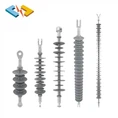

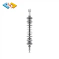
1. In ultra-high voltage (UHV) transmission lines, insulators not only bear heavy mechanical loads but also must meet electrical strength requirements; their reliability directly affects the safe operation of the transmission line. Furthermore, insulator strings must also meet electromagnetic environment requirements, including those related to radio interference. In UHV transmission lines, the electric field distribution along the insulator string is uneven, with severe electric field distortion, particularly near the conductor-side insulators where the electric field strength is relatively high. This causes corona initiation and electrolytic corrosion in the insulator string to often begin at the conductor-side insulators. Installing well-designed corona rings and shielding rings can effectively improve the electric field distribution of the insulator string, providing anti-corona protection.
Commissioned by Wuhan Line Power, the State Key Laboratory of Electrical Insulation for Power Equipment at Xi'an Jiaotong University conducted finite element three-dimensional electric field distribution calculations on a 1000kV AC rod-type suspension composite insulator.
The calculations employed finite element and boundary element numerical methods, utilizing powerful finite element analysis software and workstations with robust solid modeling, solution, data analysis, and processing capabilities to perform three-dimensional finite element potential and electric field distribution calculations for a 1000kV AC rod-type suspension composite insulator.
Numerical methods for electric field calculation mainly include the finite difference method, finite element method, charge simulation method, and boundary element method. The finite element method is a numerical solution method for differential equations, initially used to handle structural mechanics problems. In the mid-1960s, the finite element method was applied to solve electrostatic, magnetic, and current field problems with complex boundaries in electrical engineering.
2. The calculation model is based on the AC 1000kV rod-type suspension composite insulator drawings and related parameters provided by Wuhan Laine Transmission and Transformation Equipment Co., Ltd. A three-dimensional solid model was created according to the actual dimensions of the 1000kV line towers, insulators, conductors, and fittings, taking into account ground conditions and equipotential rings.
The 1000kV AC rod-type suspension composite insulator uses straight-line goblet-shaped towers. The side phases are suspended using a single-connection I-type structure, and the middle phases use a single-connection V-type structure. The insulator string length is 9500mm, and the conductor is LGJ-500/35 steel-cored aluminum stranded wire with an eight-split structure and a sub-conductor spacing of 400mm. The structural dimensions and model of each part are as follows.
Electric field distribution
Calculation model of 1000kV AC rod suspension composite insulator


3. Conclusions
Based on the calculations of potential and electric field distribution and the study of corona ring configuration for 1000kV AC rod-type suspension composite insulators, the following conclusions are drawn:
1. Due to the influence of towers, conductors, ground, and environmental conditions, the electric field distribution of 1000kV AC rod-type suspension composite insulator strings is uneven. The electric field distortion is severe on the conductor side, while the electric field is relatively low in the middle and tower sides. The electric field experienced by the insulator skirts and air on the conductor side is higher than that in the middle. A reasonable configuration of equipotential rings can effectively improve the electric field distribution on the conductor side of the insulator string.
2. When both large and small grading rings are configured, the maximum electric field strength near the conductor side of the composite insulator of phase I is approximately 290 V/mm, while the maximum electric field strength on the tower side is less than 100 V/mm. The maximum electric field strength occurs on the outer surface of the large grading ring on the conductor side, reaching 1388 V/mm; the maximum electric field strength on the surface of the grading ring on the tower side is 445 V/mm.
3. When both large and small grading rings are configured, the maximum electric field strength near the conductor side of the composite insulator of phase V is approximately 320 V/mm, while the maximum electric field strength on the tower side is less than 30 V/mm. The maximum electric field strength occurs on the outer surface of the large grading ring on the conductor side, reaching 1626 V/mm; the maximum electric field strength on the surface of the grading ring on the tower side is 55 V/mm. The above configuration is relatively reasonable, and the electric field distribution of the insulator is relatively uniform. 4. Due to the shielding effect of the tower and the large corona ring on the tower side, the electric field strength on the tower side of the composite insulator is relatively low and the electric field distribution is relatively uniform. The effect of the small corona ring is not obvious. Therefore, the small corona ring does not need to be installed on the tower side.