
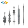

Although initially finding use primarily in polluted service areas, composite insulators have seen growing application in relatively clean environments as well due to their comparative ease of handling and attractive acquisition costs. More recently, voltage upgrading as well as compact design of new AC lines have become additional niche areas where composite insulators are being applied in clean environments.

In the case of the latter applications, insulator arrangements are often designed relatively short to fit into the reduced space window of towers. Therefore, limiting maximum E-field becomes more critical still. Another growing area of application are composite station post insulators, especially those having a solid core since these do not differ much in flange design from composite line insulators.
Three criteria have to be taken into account to assure optimal dimensioning of composite insulators equipped with grading rings:
1. Limiting electric field on grading ring & end fitting;
2. Limiting electric field along surface of insulator housing;
3. Limiting electric field at ‘triple point’ (where air & housing meet metal fitting).
All three are normally verified by E-field calculations, the first by the standard RIV test described in IEC 60437 2nd Edition (1997-09). The third criterion cannot be verified by a test while the second is as yet not verifiable by any test. Power supply companies, however, are now increasingly interested in having such verification.

Establishment of Criteria for Maximum E-Field
There is still comparatively little data published on maximum permitted E-field in the case of composite insulators. According to CIGRE Brochure 284, maximum E-field on the surface of a composite insulator (i.e. at the tip of the first shed from the end fitting) is estimated between 0.6 and 1.0 kV/mm. But this range is probably overly optimistic. For example, earlier research by EPRI indicated that a maximum limit on E-field of 0.45 kV/mm is preferable while past research at STRI proposed 0.4 kV/mm. Others have estimated critical E-field level at only about 0.38 kV/mm.
For maximum E-field on the metal fitting, the CIGRE Brochure recommended a limit of 2.2 kV/mm. According to an earlier paper from EPRI, the value indicated for surface E-field on metal fittings and grading rings should be 2.1 kV/mm and this value is often being used as a reference for design purposes. According to internal past CIGRE discussions, however, some utilities are specifying values as low as 1.6 kV/mm – probably to account for possible manufacturing defects, surfaces that have become slightly damaged from improper handling or ageing of the grading rings in service. In an earlier paper, STRI had recommended 1.8 kV/mm.
Recent Data from STRI & EPRI
More recent research summarized work carried out to determine a practical limit for permissible E-field on insulator surfaces for design purposes. Initial work by EPRI to determine E-field threshold levels for water-induced corona (first published in 1999) was expanded based on small as well as full-scale tests to refine these thresholds. For example, results from both natural ageing tests (at STRI) and artificial ageing tests (by EPRI) showed a clear tendency for reduced hydrophobicity on sheath sections where E-field exceeds about 0.3 to 0.4 kV/mm (see Fig. 1). Further fine-tuning of the threshold has been based on small-scale and full-scale laboratory tests as well as data from service experience. This led to the following final criterion, illustrated in Fig. 2: average E-field on the insulator sheath should not be permitted to exceed 0.42 kV/mm for more than 10 mm along the surface. Such an averaging approach was introduced to avoid small yet significant geometry issues, which do not properly reflect insulator performance (i.e. there will be a sharp increase in E-field at such points). As for the end fitting seal (i.e. the triple point), E-field must not be allowed to exceed 0.35 kV/mm. Calculations should be modelled using 3-D E-field simulations and laboratory testing can also be considered.

Finally, the following criteria were used for many practical applications:
• Limit of E-field on grading ring & end fitting: 1.8 kV/mm
• Limit of average E-field along housing surface: 0.42 kV/mm
• Limit of E-field at triple point: 0.35 kV/mm

Explanation of Approach
Program & Modelling
All calculations at STRI were performed using the Comsol Multiphysics software program. A practical example of such a calculation for real service conditions was as follows:
The insulator cross-arm model was fitted on the centre phase on one side of a tower (as in Fig. 6). The phases were arranged to simulate the worst-case scenario from an electric field point of view, i.e. the centre phase is exposed to the highest E-field due to proximity of the adjacent two phases on the same side of the tower. According to the requirement of the client, the voltage was set to Um=420 kV. The electric potential applied in the centre phase was therefore 420/√3 kV. Voltage on the two phases above and below the centre phase was 420/√3 kV with a 120° phase shift. Only 10 to 12 shed pairs are normally modelled, based on earlier experience with similar calculations, which showed that only those sheds closest to the fittings are exposed to the highest electric field. Making this assumption allowed modelling time to be reduced.
The two main materials taken into account for this calculation were air and silicone rubber. The dielectric constant (relative permittivity) used for the glass fibre rod is the same as for silicone, i.e. 3.0, but since actual relative permittivity is lower for silicone, the calculation is slightly conservative. The most important reason to simplify calculations in this manner is to make meshing easier and allow the calculations to run faster. Fig. 3 shows typical results.
